


Manhole Connectors for Polyethylene Pipes
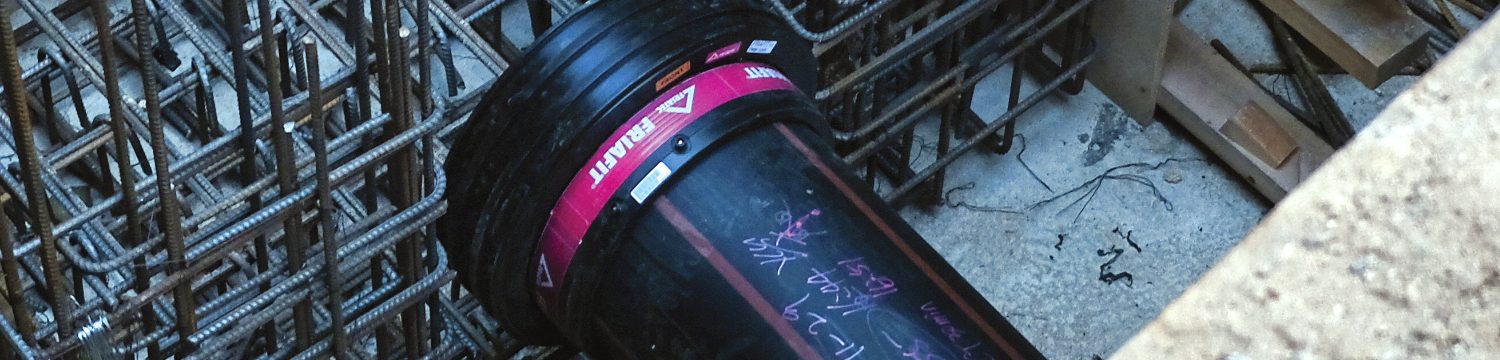
Manhole Connectors fix PE pipes into Concrete chamber walls. A connector is necessary because, unlike rigid Ductile Iron or Clay pipes, PE pipes are subject to ongoing movement through temperature change and ground settlement. This causes small but constant changes in pipe length. This combined with expansion of the pipe OD as the concrete cures, means there is always a gap between the concrete and the pipe. If a manhole connector is not used, sewage and waste water will continuously leak from the chamber, polluting ground water, leading to erosion and sinkage.
There are two DSD approved connection methods given in the DSD PS Appendix 5.6-5 and PS Appendix 5A, Clause 5.7. These are a Type A - Flexible connection or a Type B - Rigid connection. Links to the DSD Drawing for Manhole connections and the material specification and design are given below.
DSD PS Appendix 5.6, Page 5 (Drawing only)
DSD PS Appendix 5A (Full specification)
DSD PS Appendix 5.6 (Boundry Specification
Which one do I choose? Use Type A connection on sizes up to DN 525, UNLESS: the installation is in reclaimed land, the pipe is installed above ground or there is a steep slope between chambers. Further explanation and examples of this are provided below.
Type A - Flexible Connection
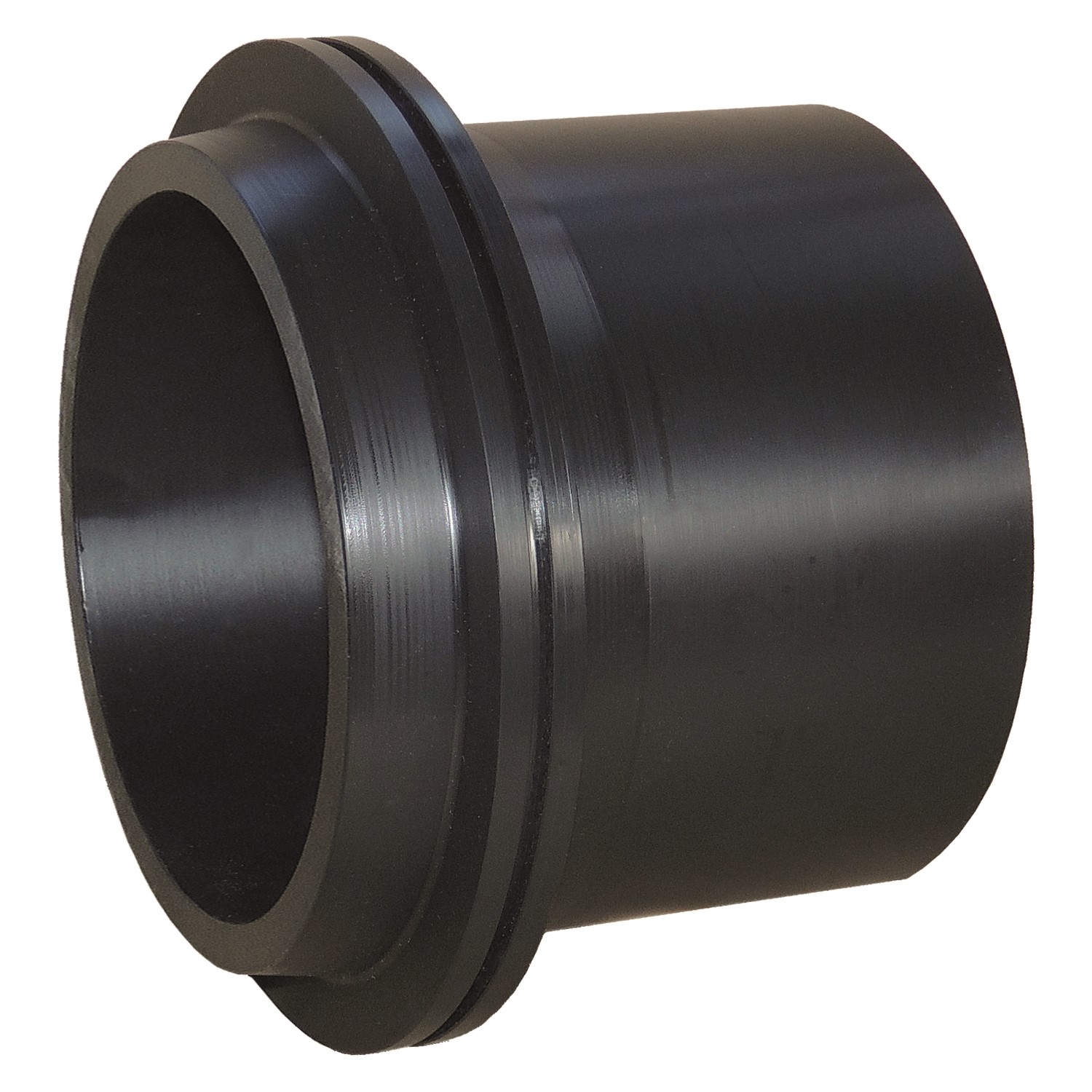
Also known as a Sliding Manhole Joint, this comprises of two machined PE components, independant of each other. The socket ring is plastered into the concrete chamber (non structural) and the spigot fused onto the PE pipe. The two components seal with O'Rings and a Hydrophilic expansion seal. This joint allows the pipe and spigot to move independently of the Socket ring in the chamber.
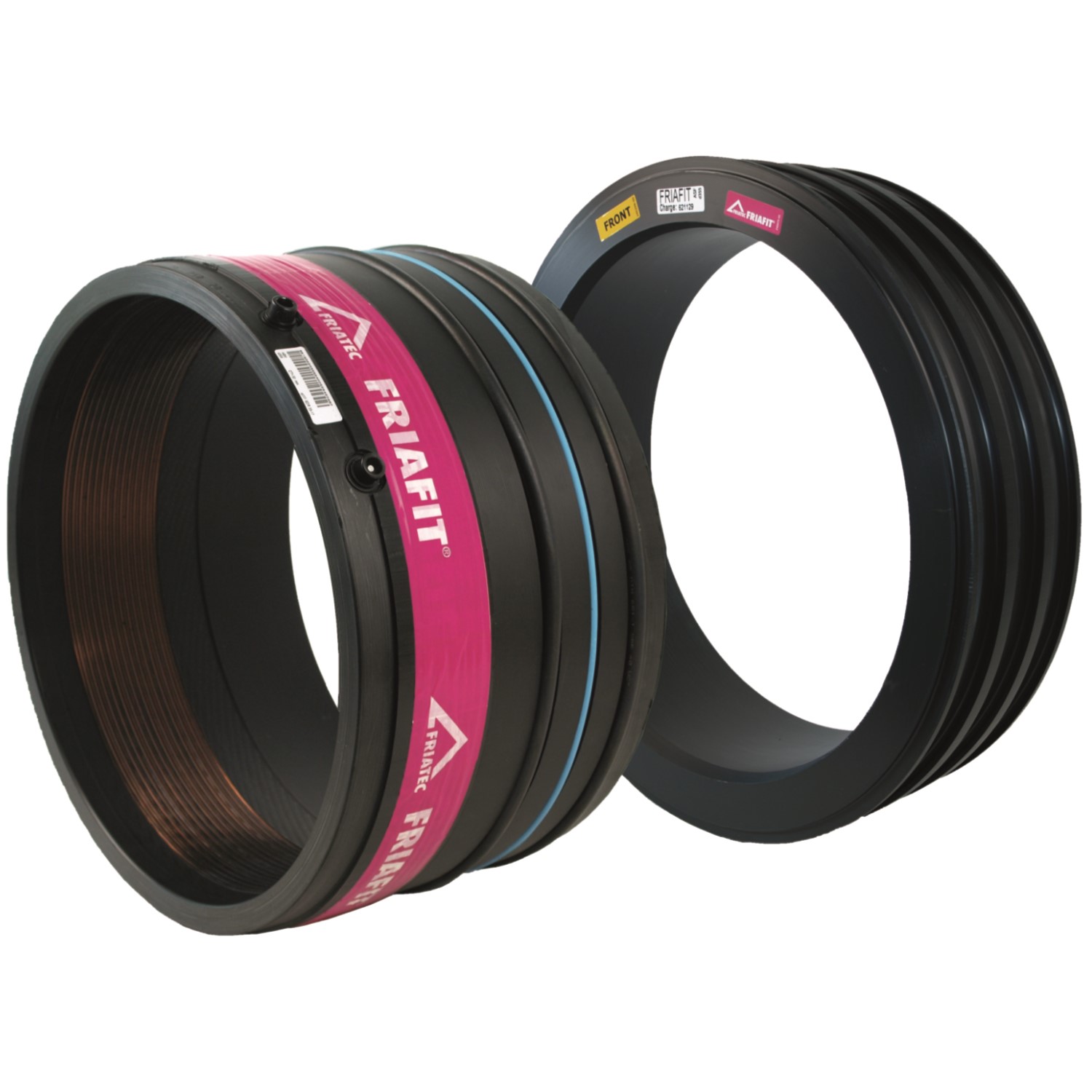
Movement due to temperature change (thermal movement) and settlement forces causing small changes in the pipes length or angle, are not transferred into the chamber wall. These Socket/Spigot type joints allow for some vertical deflection (≤ 3º), so the chamber and pipe can settle independently of each other, the pipe can change in length due to temperature, while still maintaining a water tight joint with up to 5m of head. Typically only used in sizes up to DN525, larger sizes a Rigid Type B joint is typically used.
-
![Sliding Manhole Joint]() Flexible Manhole Connector (Fabricated)
Flexible Manhole Connector (Fabricated) -
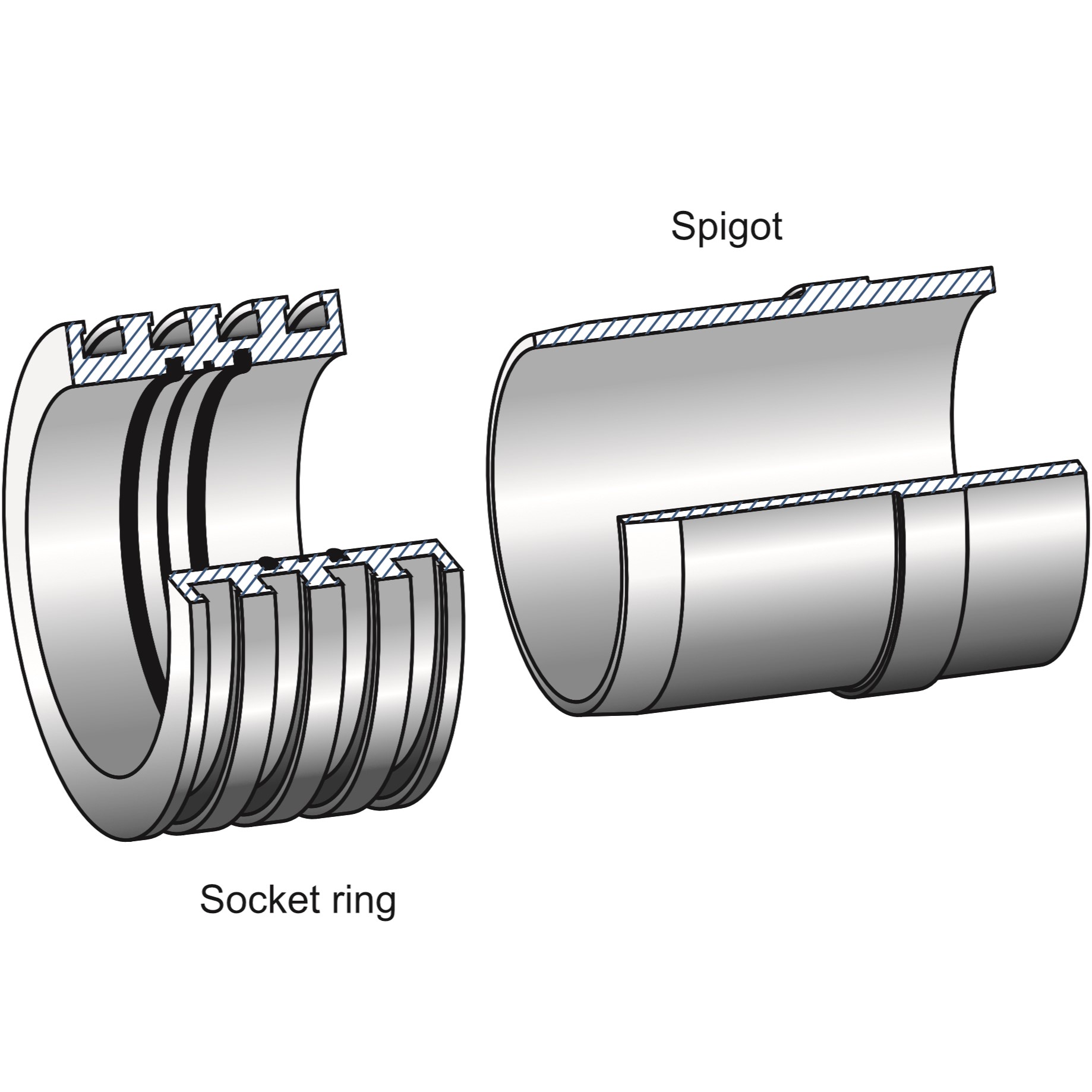
![AEM ASF]() Flexible Manhole Connector (Friatec)
Flexible Manhole Connector (Friatec) -
![Manhole Connection – Installation (1)]() Flexible Manhole Connector Installation
Flexible Manhole Connector Installation
Advantages and limitations of Type A
Advantages of Type A Connections - In a Type A joint, the spigot end is welded to the pipe. When movement caused by a temperature change in the fluids, traffic loading or soil movement is applied, the spigot is free to slide a small amount inside the sockets rubber rings, but still maintain a watertight seal.
This flexible design means no force is applied to the socket ring or the chamber wall from pipe movement, therefore the socket ring can simply be plastered into a hole in the chamber wall (non structural install). The socket ring does not need to be tied in with reinforcing or poured with the wall, as there are no forces applied to the socket ring by the pipes movement.
Type A Flexible joints can be quickly installed as no structural Concrete / reinforcement / Corbels are required, the contractor can simply make a hole in an existing cast chamber wall and plaster the socket ring in, as the pipe is laid. See the images & Video below showing typical applications.
Limitations of Type A Connections - Type A joints are not suitable in reclaimed land, as change in the length of the pipe due to ground settlement will be greater than the spigot length, also not suitable if all or part of the pipe is above ground, as large temperature changes may generate significant length change in the pipe, both situations could pull the spigot out of the socket ring over time. Not recommended for installations where there is steep gradient between chambers (installed down a slope).
In the cases above, a Type B rigid joint should be cast into the chamber wall, integrated with the reinforcing, to create a structurally anchored connection. This anchors the pipe ends into the chambers and settlement is taken up in the pipe, which self relaxes when ground movement or settlement occurs.
Type A Flexible Connection Project example A
Type A Flexible Connection Project example B
Type B / Rigid connection / Single or Double Spigot
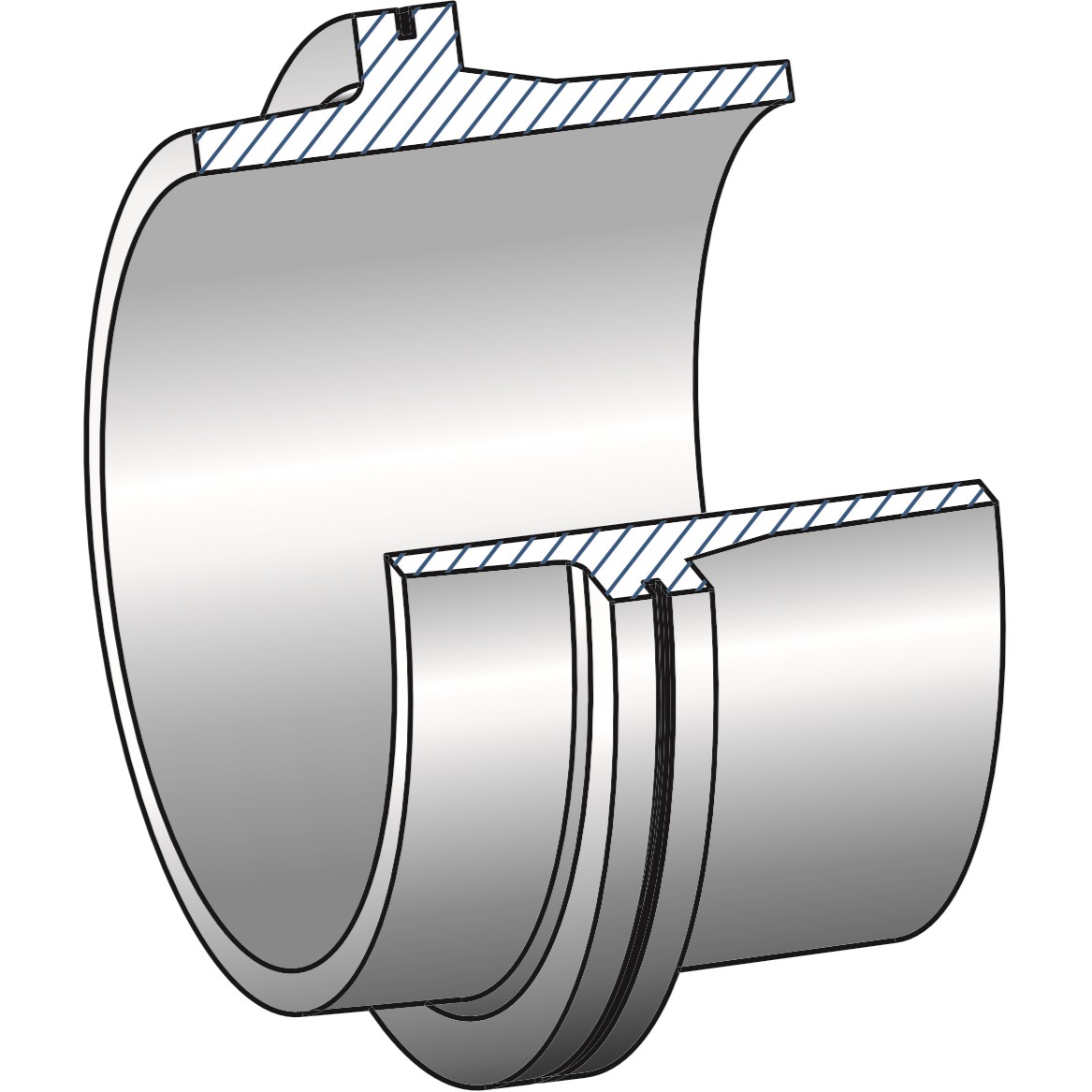
Using the same principal and dimension relationships as a PE puddle flange, a Type B rigid manhole joint is machined from a single piece of hollow PE100 bar, with an embedded hydrophilic seal ring on the puddle edge. The theory of anchoring PE using puddle flanges is given here. The principal is that under tensile stress, the pipe will fail before the puddle pulls free of the concrete. Type B joints must be used in reclaimed land where future ground settlement will slowly stretch the pipe between chambers.
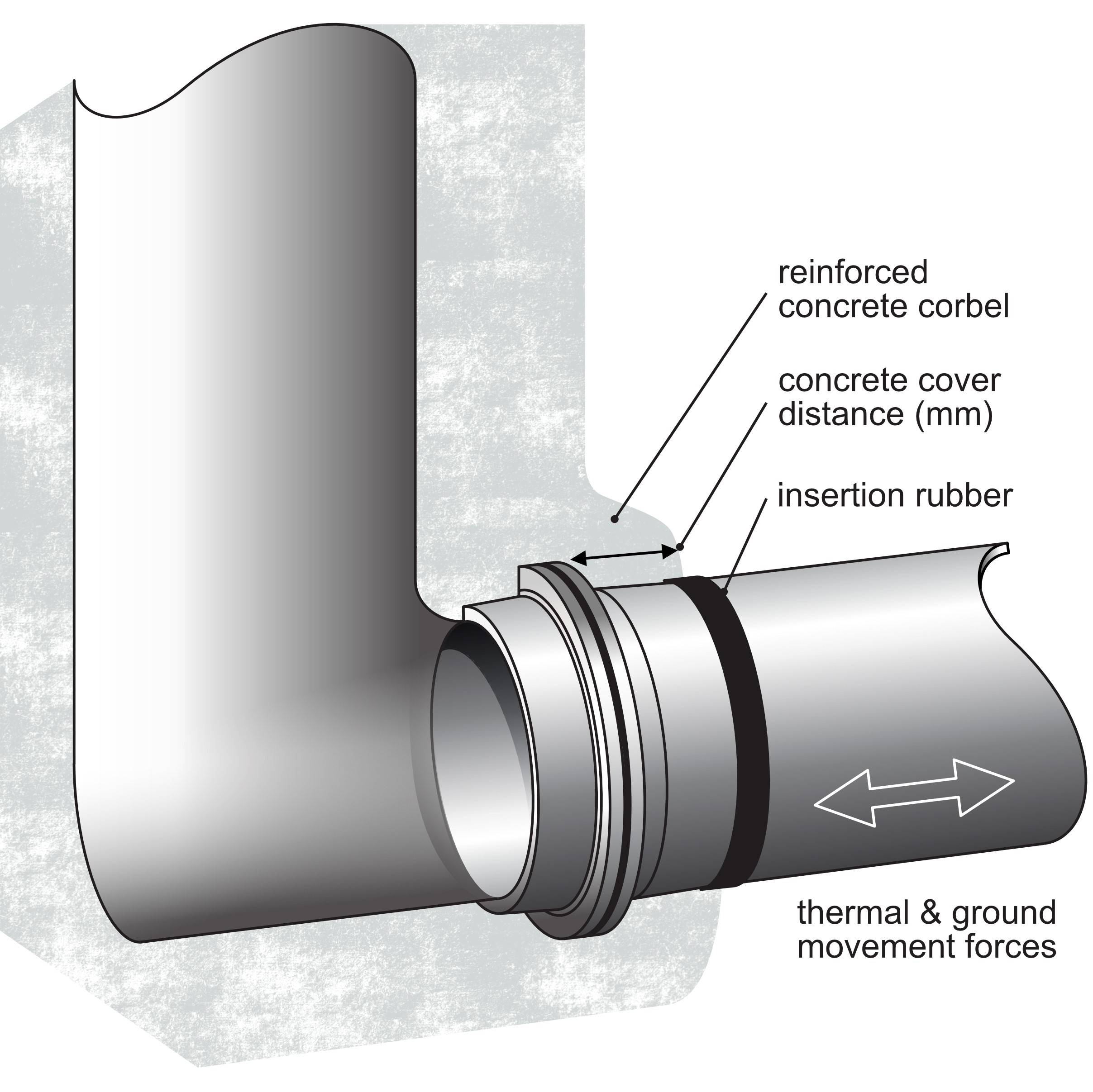
Type B joints should be wrapped with 6-10mm thick of insertion rubber, at the PE-Concrete interface during pouring of the chamber, to protect the PE from point loading on the concrete edge during deflection (see image below, for further information refer to Australian Standard AS/NZS 2566-2 Installation of Buried Flexible Pipelines, Figure 5.6)
-
![Manhole Type B Short]() Short Type B - Rigid Manhole Connector
Short Type B - Rigid Manhole Connector -
![Type B Rigid Iso Plain]() Type B (Hydrophilic seal not shown)
Type B (Hydrophilic seal not shown) -
![Manhole Connection – Type B]() Rigid Manhole Connector Installation
Rigid Manhole Connector Installation
Advantages and Limitations of Type B
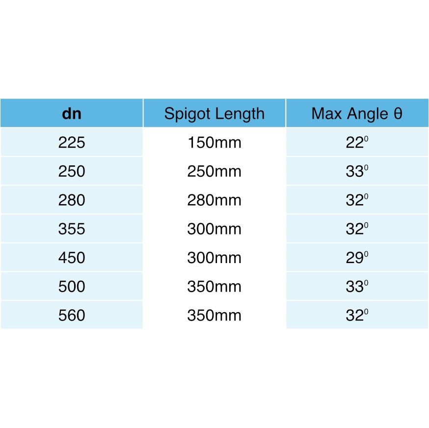
Advantages of Type B Connections - Type B joints are typically cast into the chamber wall (not plastered in place like Type A) and when integrated with reinforcing steel and have sufficient cover, can withstand 100% of the maximum tensile force applied by the pipe. Type B connections are designed for reclaimed land, steep slopes, or where the pipe is installed above ground. Type B / Double Spigot series can be cast into the wall on an Angle up to 30º and the excess spigot cut off after cured in place, saving repair plastering inside the chamber.
Limitations of Type B Connections - Because they are a rigid connection, the forces created by temperature change in the pipe (length change) are transmitted directly into the chamber wall. Therefore, Type B connections should to be cast into the wall when the chamber is poured. In addition, the chamber wall must have sufficient cover over the puddle flange to transfer the tensile forces into the wall and back against the soil face. This may add construction expense and means the PE pipe installation must be performed during chamber construction, unlike a Type A connection.
NOTE: Plastering a Type B Connection in place may not withstand the forces and could break the PE connector out of the chamber wall over time. Breakout forces can be calculated by considering the temperature change, the length between the chambers and estimated soil friction. Refer to our chart on the 'Concrete Cover' required to withstand full tensile loads here or contact us to assist with breakout calculations
Type B Rigid Connection Project Example


Puddle Flange specifications can be found in full here.